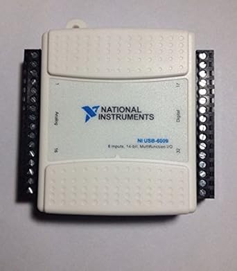
Assuming that MAX recognizes the device, you can now run a self-test of it by selecting Self-Test in the menu. You can create a task for analog output in the same way, that is, by selecting Create Task in the right-click menu of the USB device as it appears under Devices and Interfaces , see Figure 8. Tasks and virtual channels can be given any name e. In this dialog window, select the option for automatic install. The following relevant documents can be found at http:
| Uploader: | Zulukora |
| Date Added: | 17 December 2004 |
| File Size: | 9.74 Mb |
| Operating Systems: | Windows NT/2000/XP/2003/2003/7/8/10 MacOS 10/X |
| Downloads: | 49288 |
| Price: | Free* [*Free Regsitration Required] |
The New Data Acquisition Device dialog window. When the wizard has finished the installation of the driver software, the USB is ready for use after you click Finish Norwegian: Digital input DI and digital output DO: Note how the task value the magenta coloured line is propagated through the relevant nj.
We will perform a very simple test, which is sufficient if we are to check that both AO0 and AI0 faq correctly. To prepare for the loopback test, we wire together AI0 and AO0. Input high is between 2. The wizard has finished the installation of the driver software, and the USB is ready for use, after you click Finish Norwegian: Most of these are described in the following.
In this dialog window, select the option for automatic install. Special USB features are described separately. In general, a task can contain one or more global or local virtual channelsand one such virtual channel is based on one physical channel having e.
NI USB-6009
This document shows in detail how USB must be connected to external signals for measurement or control. Here is a video that shows the steps: If a global channel is reconfigured, all tasks which involve that global channel are updated accordingly. In rdiver folllowing it described how to create tasks for the analog input and the analog output operations.
However, here I assume that you select Cancel. The configuration can be saved using the Save button, see Figure On-board voltage sources available at individual terminals: Figure 7 shows MAX. If you had written a value outside this range to the DAQmx Write function you would get an error due to signal limitations function it can only drivver voltage outputs between 0 and 5 volts.
Via the Polymorphic VI Selector driveer can select the type of data the function will write. Above we created a task for an analog input.
All these items, i. Assuming that MAX recognizes the device, you can now run a self-test of it by selecting Self-Test in the menu. Output low is below 0.

You may deselect Auto-scale chart in the window. If for some reason AI0 detects some other voltage than the value we set for AO0, then there is an error in either the AI0 channel or in the the AO0 channel, and further investigations are necessary.
Here, let us test analog output channel 0 AO0 and the analog input channel 0 AI0 to see if they work correctly.
NI USB Support - National Instruments
Selecting Create Task in the menu opens a window where you can select the measurement type, see Figure By clicking the Finish button in the window shown in Figure 15, the window shown in Figure 16 is opened where you can mi the physical channels for your task. In general, differential signal coupling is preferrable to single ended coupling due to better DC noise suppression.
In Dricer 11, an output voltage of 3. In the window shown in Figure 16, we select ai0which opens the window shown in Figure Voltage range is 0 - 5V fixed. This menu also has an import option. Window where you can enter the name of the task.

Comments
Post a Comment